For the planar exact constraint toy, I decided to explore the effect of contact radii and contact stresses on 2D planar pseudo-kinematic couplings (KCs).
Before diving into the toy concept, I briefly want to talk about contact stresses. No two surfaces are perfectly matched. Even if one is molded on the image of the other, there are still imperfections that can arise from oxidation, thermal stresses, body forces, or contaminants. Consequentially, the interface between two surfaces is an amalgamation of point and line contacts. When any force is transmitted across the interface, the point and line contacts (having theoretically zero cross-sectional area) must deform to bear the load at a reasonable stress. In other words, elasticity is the reason why most things fit together or line up (the classic example of this being a 4 legged chair). Taken to another extreme, the contact between two surfaces can be limited to just a few point or line contacts to localize the deformation that must happen to the surfaces to align. If the constrains imposed by the contacts properly matches the desired number of kinematic degrees of freedom, the interface is considered properly constrained. If there are to few constraints, the interface is under-constrained. If there are too many constraints, it is over-constrained. For an interesting discussions of constraints, flexures and couplings, check out John Hopkins’s PhD Thesis on FACT and Layton Hale’s PhD Thesis on precision machine design.
I’m calling the structural interfaces in the toy ‘pseudo-kinematic couplings’ because the couplings are over-constrained since that are not perfectly 2D. The third dimension of extrusion turns the point contacts into line contacts. Three perfect line contacts can properly constrain an object, but no line contact is perfect (surface roughness, machining error, etc.) and the interface becomes over-constrained. This is the beauty of creating point contacts between surfaces where at least one surface has positive Gaussian Curvature (or you can be clever and use two cylinders with orthogonally oriented axes, also on the linked wikipedia page). Of course, smaller contact points increase the contact stress and can damage the surfaces. Another example of ‘Conservation of Screwedness’ introduced to me by Professor Oscar Mur-Miranda.
Two quick and important equations on Hertz Contact Stresses for line contacts taken from Professor Alex Slocum’s FUNdaMENTALs, page 17.
Line contact patch size:
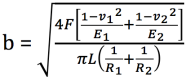
and maximum pressure (stress) along the center of the contact patch:

One very important in the above equation for contact patch size is the 1/R terms in the denominator. They are the radii of curvature for the two contacting surfaces. Small radii make for small contact patches, and large radii (or radii in opposite directions) make for larger contact patches. The contact patch affects the magnitude compression at the interface and the acceptable load that can be transmitted before the damage to the surfaces becomes large.
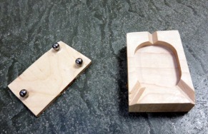
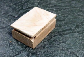
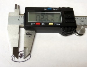
To explore the role that contact stresses play in KCs, I designed and made a maple plate with identical contact points and different contact radii. 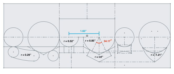

The analysis for the reaction forces under different loading conditions can be seen here. To explore the effect of contact patch size on any additional friction, this KC was specifically designed to have low lateral load resistance. However, as the vertical load is increased, the reaction forces become able to resist some lateral loading.
Ultimately, the left hand KC (the one with the small circles) felt capable of providing the greatest additional friction against lateral loading. This makes sense, because greater contact stresses dig into the material more. However, without a proper way to control loading (say a spring), there is no way to be rigorous about testing the frictional resistance.